Written by Rohit Sati M.Sc | Product Manager-Containment & Enclosure
The Electrical Leak Location method is a very sensitive technique that accurately locates leaks (if they exist) in geomembrane liners in landfills or impoundments. This field-proven method has located many leaks not previously found using conventional methods. Layfield supplies Leak Location surveys across North America. Leak location surveys are effective for both exposed and backfilled geomembranes. The Electrical Leak Location method works on all polymeric geomembranes. The method is ineffective on GCLs or compacted clay liners that do not include a geomembrane. Once you detect leakage in a sump or monitoring well, localizing and repairing the leak can be difficult. The Electrical Leak Location method is the fastest and most accurate technique to pinpoint the leakage. There are several leak location methods available for testing the integrity of geomembranes. These methods can be used right after the installation as a final quality check; or as part of a future maintenance program.
Single Lined Systems
Electrical Leak Locations methods all rely on the geomembrane being an electrical insulator. An electrical charge is introduced between the top and the bottom of the geomembrane. The leakage of current will show the location of discontinuities in the geomembrane. This method works on single-lined systems where the geomembrane is in direct contact with a moist conductive soil subgrade such as compacted clay, a GCL, or other fine-grained native soil. If the subgrade is not conductive (frozen, poorly graded gravel, or too dry), a method of making it conductive will be required (see double-lined systems below). Electrical methods will often require some changes to construction details for the best effect. Exposed concrete, batten bars, or other structures within the lined area will show “leaks” to the sensor equipment. Concrete and batten bars should be cap-stripped, and pipe penetrations should be constructed to be electrically isolated during testing.
Water is often used to create the electrical potential on top of the geomembrane. There are three electrical leak location survey methods in use that use water.
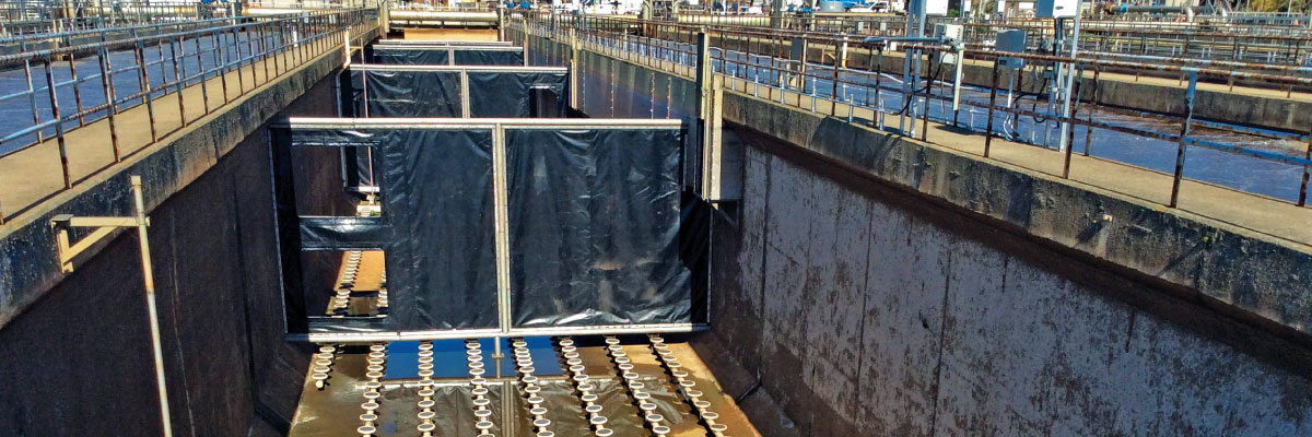
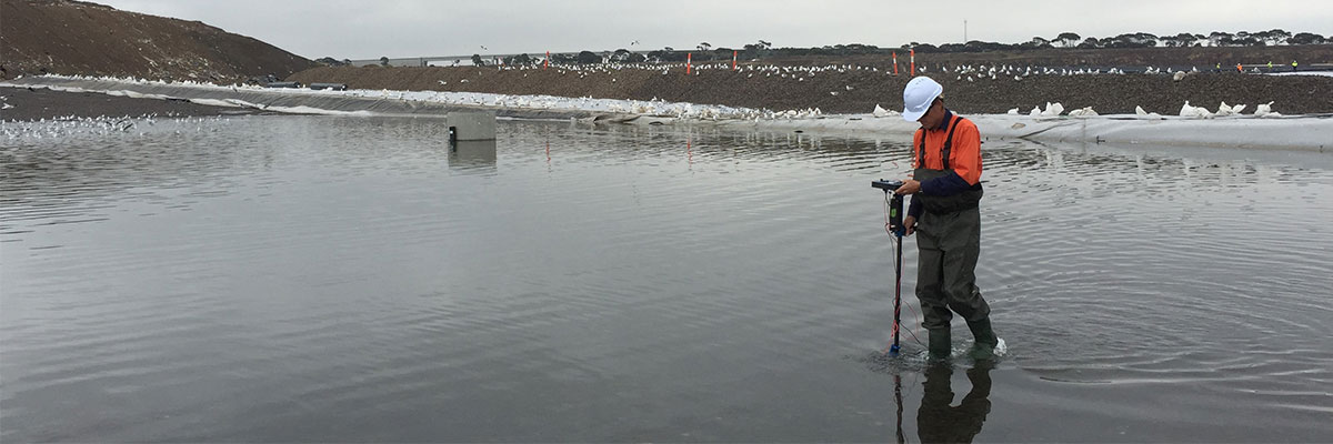
In the water survey (ASTM D7007), water is placed inside the geomembrane, and an electrical potential is induced between the water and the ground. Current leaks will show discontinuities. The most accurate survey is a wading survey in 2 to 3 ft of water. Scanning a full pond with a towed sensor from a boat is also possible. The water survey method has been used for over 30 years and is very accurate. The main drawback of this survey is the cost of water. It is expensive to fill a pond with water for the survey only to have to draw it down again for repairs found by the survey. Water surveys work best when multiple ponds cycle through use, after ponds are put into service, or as the pond is being drawn down for maintenance.
In the water lance survey (ASTM D7703), electrically charged water is sprayed from a water wand onto the surface of the geomembrane. If a discontinuity exists, the water penetrates the ground and completes a circuit. Water is delivered from a tank or recycled from a low spot on the geomembrane. The water lance is frequently used to scan the slopes of ponds, especially when a water survey or water puddle method has been used on the base.
In the water puddle method (ASTM D7002), electrically charged water is pushed ahead of a squeegee to make contact with the geomembrane. If a discontinuity exists, the water penetrates the ground and completes a circuit. Water is delivered from a tank or recycled from a low spot on the geomembrane. The water puddle method is used when testing needs to be done before the pond is filled with water as an alternative to the water survey.
There are variations of electrical leak location methods for single-lined systems that do not use water.
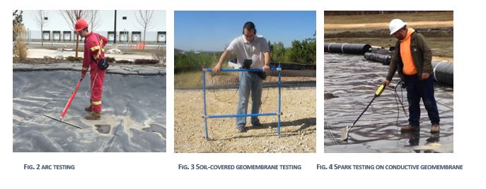
A conductive geomembrane survey (ASTM D7240) can also be done on a single-lined system. A specially constructed geomembrane with a bottom conductive layer is used in this case. Current is induced into this conductive layer, and discontinuities show as sparks. This survey type works best on clean, dry geomembrane and does not require a conductive subgrade. Conductive geomembranes can effectively detect discontinuities in the body of the sheet. However, isolation of seams to prevent false positives and isolation at the perimeter of the conductive geomembrane can require rework at the anchor trench if leak testing (such as a water survey) is needed in the future.
The arc survey method (ASTM D7953) uses proprietary equipment to scan a geomembrane without water. In practice, the equipment operates almost the same way as the water puddle method; however, no water is needed. This equipment shows a spark and a signal from the detector when a discontinuity is found. This survey type works best on clean, dry geomembrane. It does not require a conductive geomembrane. Once the pond is in operation and filled with water, a water survey is more appropriate.
In the soil survey (ASTM D7007), the soil on top of the geomembrane is charged with electrical potential. Electrodes are then used to scan the backfill, showing a change in potential near a discontinuity. Soil surveys effectively find construction damage due to backfilling in covered geomembranes. One note about a soil survey is that an electrical break needs to be made between the backfill and the ground. This is usually accomplished by leaving the anchor trench open during the survey. If subsequent surveys are required, the geomembrane is usually exposed again at the anchor trench before surveying begins. Once the pond is filled with water, a water survey can be used for subsequent testing; however, the geomembrane in the anchor trench will still need to be exposed to make an electrical break. At the time of installation, it is possible to create a detail at the perimeter that maintains the electrical break for future testing without excavating the anchor trench.
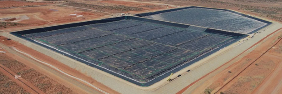
Double Lined Systems
There are several complications in geomembrane systems with more than one layer of geomembrane. The secondary geomembrane layer electrically isolates the primary geomembrane from the ground, and making electrical contact for testing the primary liner becomes difficult.
The secondary liner (placed on the prepared subgrade) can be tested in double-lined systems using the above electrical methods.
Testing the primary liner requires adding an electrically conductive element between the primary and secondary geomembrane. Flooding the leak detection zone has been used in the past to make it possible to perform electrical leak location surveys of the base of impoundment. Water is placed between the primary and secondary geomembranes before the survey. One issue with this method is that the water in the leak detection zone can take a long time to drain (many months and sometimes years). If the leak detection zone is to be flooded, it is suggested that the water used has different properties from the water contained in the pond. This helps to differentiate potential leakage during the drainage period. Flooding the leak detection zone cannot be used to test side slopes.
Once in service, the leak detection zone will show leakage if a defect exists. Leakage in the leak detection zone provides the conductive layer needed for a water survey. A water survey can often be used in maintenance even though a different method may have been used during installation.
In composite systems (multiple layers of geomembrane/clay or geomembrane/GCL), compacted clay or GCL underneath the primary geomembrane can form the conductive layer. The conductive element must be in direct contact with the bottom of the primary geomembrane for effective leak location. Since many landfills use composite liner layers creating the electrical potential required for testing is often simple as reviewing the placement of these layers.
Electrically conductive geotextiles are available that can be used to create the electrical potential under the primary geomembrane (ASTM D 7852). These electrically conductive geotextiles can be added as a separate layer or combined with drainage composites. The conductive layer should be closest to the top to contact the primary geomembrane.
Conductive geomembranes (ASTM D7240) can be used for testing the primary geomembrane in double-lined systems. The specially constructed geomembrane with a conductive bottom layer is used as the primary liner. Current is induced into the conductive geomembrane using a grounding pad on the top surface, and a spark tester is used to scan for discontinuities. During installation, great care must be taken to isolate the top and bottom surfaces of the geomembrane electrically. False positives are common with this type of material, and these false positives must be isolated and repaired before a complete scan can be completed. Problems with electrical isolation at the perimeter of the conductive geomembrane can require rework at the anchor trench if leak testing (such as a water survey) is needed in the future.
The Vacuum Acoustic Leak Identification (VALID) method is a test designed explicitly for double-lined systems. It is designed to simultaneously test both the primary and secondary liners in a double-lined system using a single survey. In the VALID method, the top and bottom geomembranes are joined at the perimeter by welding or mechanical means. Then a vacuum is applied to the interstitial space between the geomembranes. The top surface of the geomembrane is scanned with ultrasonic microphones that pick up the distinctive sounds of a vacuum leak. Vacuum leaks can be detected in the primary or the secondary liner with this method. The VALID method works best on clean, dry geomembrane and does not require a conductive subgrade.
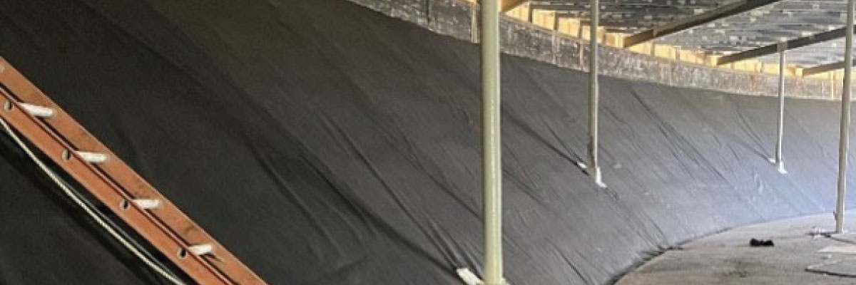
GeoVolt™ is a conductive geotextile to detect electric leaks for any non-conductive geomembrane containment.
It is important to note that the previous tests can only be used in specific scenarios. Each scenario is dependent on the materials specified, as well as the design and application of the system. Layfield has developed a product to limit these variables, making leak detection testing independent of material selection or design. The GeoVolt™ is a patented conductive geotextile solution that can be placed underneath any non-conductive geomembrane to perform leak location testing immediately after it has been installed or after it has been in service for any period. No need for a water source if the containment is tested using spark and arc testing. The geotextile itself has a conductive top layer with a layer and a cushioned non-conductive bottom layer. The edges of the geotextile have a unique design that continues the conductivity across the overlap when installed. These edges can be carefully torched or sewn together to make a larger panel for ease of deployment. The GeoVolt™ has demonstrated through testing to provide a uniform conductive layer under the geomembrane. This makes it possible for the geomembrane seams to be tested. Products such as Polyethylenes (HDPE and LDPEs), Polyvinyl Chloride (PVC), PVC alloys, Polypropylene, and Chloro-sulfonated Polyethylene (CSPE) can be surveyed for leaks with GeoVolt™. This no longer limits the specifier to what materials they wish to use if a particular product is preferred. The other advantage to the GeoVolt™ is that it can be tested after the geomembrane is backfilled, immediately following the installation, or after it has been in service. A ground wire can be connected to the GeoVolt and left exposed to allow technicians to join the GeoVolt™ to the ground for future testing.
Related Articles
View All News