Background Information and Challenge
Municipalities in northern regions of the US and Canada often experience challenges with cold weather conditions that can adversely affect microbial processes in wastewater treatment facilities.
A municipality in Western Canada was impacted by the reduced nitrification efficiency of its wastewater treatment process during the winter. This resulted in the accumulation of higher than acceptable ammonia levels before the treated water was discharged into a nearby waterway. This case study presents numerous challenges during the design, fabrication and installation of a modular insulated cover (MIC) system.
There were several challenges we encountered from the beginning. One of the main challenges was to design a cover with the following design attributes:
- Be chemically resistant to wastewater.
- Meet the minimum heat retention design temperatures at the exit of each cell
- Minimum R-17 insulation minimum 150 mm thick foam
- Highly UV-resistant cover
Other challenges included:
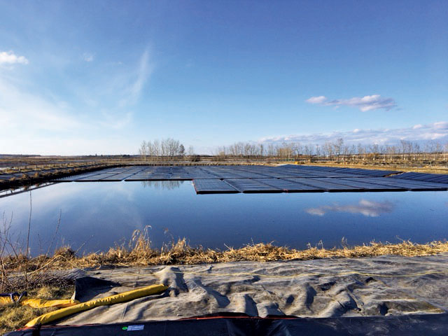
- Floating debris and vegetation in the ponds needed to be removed
- Cover design to accommodate aeration lines suspended over the water surface
Solutions and Results
1. MIC Design:
To understand the heat losses, Layfield developed a heat loss calculator to model the heat transfer with and without a cover system. The model provided us with the required insulation properties of the EPS foam. The calculations determined the project required an R17 foam to provide the necessary heat conservation at temperatures as low as -40○C (-40○F).
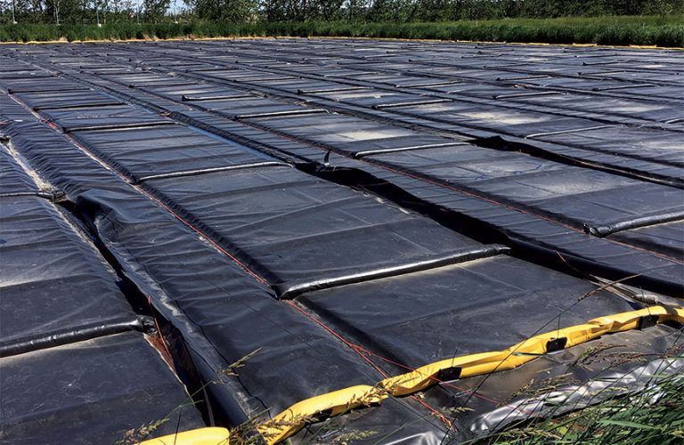
The MIC needed to be sufficiently buoyant so our field crew could deploy the covers without significant deflection. The MIC panels typically comprise expanded polystyrene foam encapsulated with a synthetic barrier on both sides.
2. Fabrication of MIC panels included:
- Encapsulation of the foam with layers of impermeable geomembrane.
- Customization panels to cover as much exposed surface area as possible.
- Testing the panel for leakage.
- Optimizing the size and weight of the panel to aid in shipping
- Custom tensile testing was performed to ensure the weld strength of the strap holding sand tubes to MIC panels.
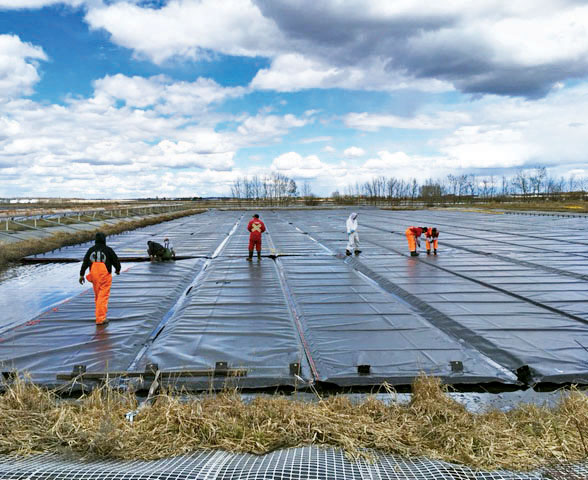
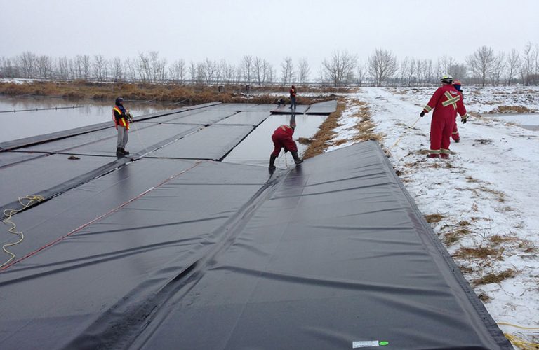
3. MIC Installation:
Installation of the MIC was carried out in phases. The 1st phase was to cover only cell #3 in December. Cells #4, #8 and #9A were required to be installed by the following June.
Installation took place in extremely cold conditions and posed challenges to our field technicians. Material handling and installation was a major challenge on the first cell (#3) as the MIC panels needed to be installed in temperatures as low as -26○C ambient, with a wind chill factor often reaching -35○C.
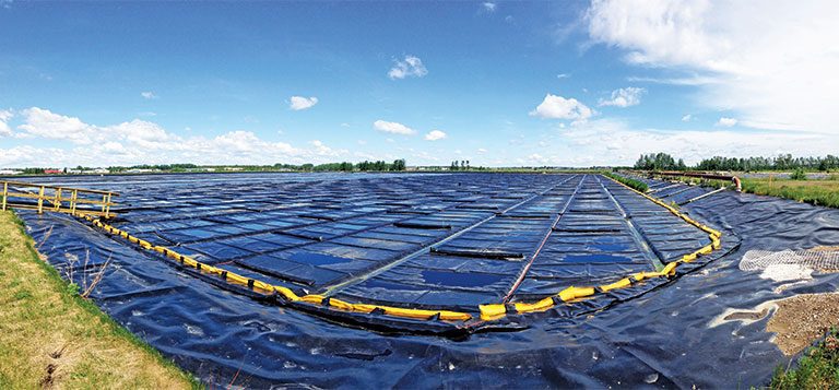
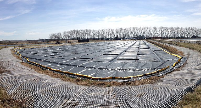
Result
The cover provided sufficient buoyancy for our field technicians and met our safety criteria. A ballast system was welded on the top of the MIC panels to minimize wind uplift of the floating MIC cover.