Technical Bulletin Provided by Amy Woods and Prabeen Joshi
Introduction
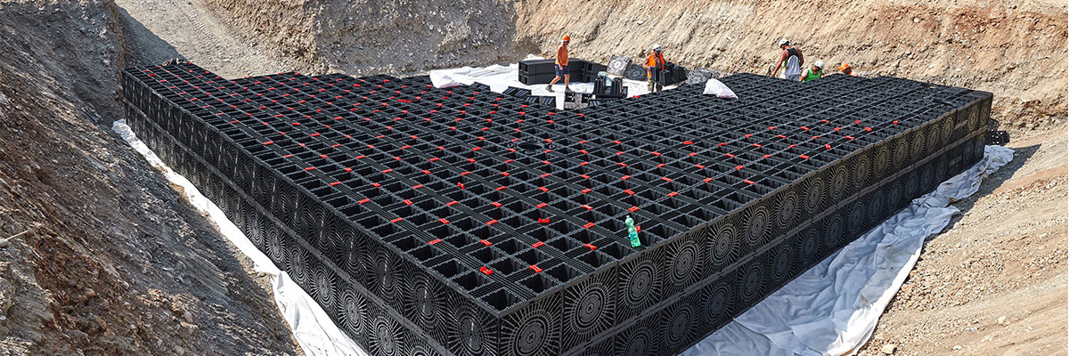
Runoff from impervious surfaces like pavement and rooftops should be managed effectively in an urban setting so that it does not flow into storm sewers and watercourses. An effective urban stormwater management practice helps precipitation from storm events infiltrate the ground or be retained to allow infiltration. Modular underground stormwater tanks have recently become a standard practice in many North American municipalities. These stormwater tanks are easy to install and are designed to allow runoff water to infiltrate or be retained to offset the impact on stormwater systems during peak flow by stormwater detention.
Several types of modular stormwater tanks are available in the market, and each of them comes with unique features, but all of them provide essentially the same function. This tech note will compare the use of two of the most common types when operating under a hydraulic trap condition (Figure 1): a Flat Bottom type with full subgrade contact and an Arched type with an open bottom. A hydraulic trap condition, in this context, is defined as the condition where the groundwater elevation is higher than the base of the stormwater storage tank (i.e., an inward hydraulic gradient).
Figure 1 Schematic shows two commonly used stormwater tanks: a) Flat Bottom type and b) Arch type with standard requirements for bedding stone and depth of cover.
Construction
A prudent construction sequencing for these modular systems includes:
- Underground excavation lined with a non-woven (NW) geotextile and backfilled with at least 15 cm (6″) of 19 mm (3/4″) clear stone that is covered by a layer of NW geotextile for the protection of overlying geomembrane.
- A geomembrane layer (typically a 0.76 mm/30 mil thick Linear Low-Density Polyethylene), followed by another layer of NW geotextile and then the modular tank system.
- Complete encapsulation of the tanks using a geomembrane and installation of a geomembrane protection layer (e.g., NW geotextile).
- 19 mm (3/4″) clear stone backfill on the sides and top (min 30 cm/12″) of the modular system, followed by the final cover to bring the system to final grade elevation.
It is important to note that the dimensions in the construction sequence are typical values and may change with the site.
Load Transfer Mechanism and Potential Issues
The two systems principally differ in how they transfer the vertical loading to the subgrade and the confinement of the underlying layers (e.g., geomembrane and gravel layer within the footprint of the tanks, see Figure 2). The arch system leaves the geomembrane and soil immediately beneath the unconfined storage chamber. In contrast, the flat-bottom modular design provides a uniform stress distribution on the geomembrane and subgrade.
The width of the unconfined zone beneath the arch system depends on product dimension and is usually between 60 – 90 cm (2 – 3 ft). Some of the potential issues that may arise by leaving these layers unconfined and possible solutions are discussed in this tech note.
Figure 2 Schematics showing the difference in load transfer mechanism between the two stormwater tank systems: a) Flat Bottom type and b) Arch type.
Potential Issues Due to Unconfined Geomembrane Layer
In a hydraulic trap condition, the groundwater level is higher than the base of the storage system (i.e., the geomembrane layer at the base), so the geomembrane will always be subject to hydraulic uplift. If designed and constructed properly, this uplift pressure would be countered by the weight of the gravel layer installed on top of the geomembrane.
Figure 3 Schematics showing the difference in bedding stone requirements under the two systems a) Flat Bottom type and b) Arch type to counteract uplift pressure.
The groundwater level is expected to fluctuate seasonally or between two storm events, during which the uplift pressure on the underside of the geomembrane is also likely to vary. This change in uplift pressure may cause the unconfined geomembrane to move up or down. Under the conditions considered during the design, this movement may be subtle. It may not appear as an imminent issue, but after numerous such cycles combined with possible aging of the geomembrane (a phenomenon by which the geomembrane progressively becomes brittle) and, in some cases, poor selection and/or installation of the geomembrane could result in the development of geomembrane defects (e.g., holes, cracks, tears, etc.).
Once the geomembrane becomes defective, there will be groundwater inflow into the storage system due to the inward gradient. At this stage, the geomembrane’s most needed hydraulic barrier function is compromised, and the storage system no longer serves its design intent.
Under significant uplift pressures, there is always a risk of the unconfined ground deforming into the void space within the modular system. The amount of ground deformation may depend on various factors such as uplift pressure, vertical stresses on top of the arches, foundation soil type, stress history, etc. This change may become irreversible, causing design failure due to permanent loss of storage volume.
Solution
Issues of possible geomembrane fatigue due to fluctuation in groundwater level, stress concentration due to “point loading,” and possible loss of volume due to the ground deformation into the void could be mitigated by providing adequate confinement on the geomembrane layer for the worst possible condition (i.e., at a maximum anticipated groundwater level). This could be achieved by increasing the gravel thickness directly on top of the geomembrane. However, this approach may require deeper excavation and additional material, which could add to the overall project cost with only a modest increase in the storage capacity.
Alternate Solution
It should not be surprising that the Flat Bottom type of tank system will eliminate the two issues identified with the Arched system. The Flat Bottom type system would directly transfer the vertical loading from the cover soil uniformly onto the geomembrane layer and restrict the free movement of the geomembrane and ground with any increase in uplift pressure.
Geomembrane Selection
Geomembrane is the most critical component in a hydraulic trap configuration, as any damage on it would follow groundwater inflow and compromise the design intent of the storage system. Careful attention should be given during selection, transport, storage, and installation QA/QC. It is crucial to remember that locating and fixing geomembrane holes during the operation of the stormwater tanks could be nearly impossible and would be cost-prohibitive in almost all cases (i.e., a complete replacement might become a cheaper option).
Layfield’s Advice on Geomembrane Selection
Some of the frequent advice Layfield’s Technical Service Team offers to our clients on the selection of geomembranes for stormwater tank encapsulation are listed below:
- Geomembranes should be thermally welded. Seams taped or held together using adhesives might fail (leak) in the short/long term.
- High-Density Polyethylene (HDPE) geomembranes are difficult to work on the bends and, if folded, may stress crack in the long term.
- Reinforced Polyethylene (RPE) is also commonly used in these applications. RPE is lined with a thin layer of Linear Low-Density Polyethylene (LLDPE), which can be easily damaged and, therefore, should be avoided.
- EPDM liners are very flexible and robust but are not compatible with hydrocarbons and should be avoided in areas where contact with hydrocarbon is possible such as parking lot surface water flow.
- Geomembranes that are flexible and can accommodate more significant strains should be selected for these applications. Potential candidate geomembranes are Layfield’s LLDPE geomembranes such as Enviro Liner®, GeoFlex™, and RPE® (with restrictions), PVC, and others.
Related Articles
View All News